| HWS
|
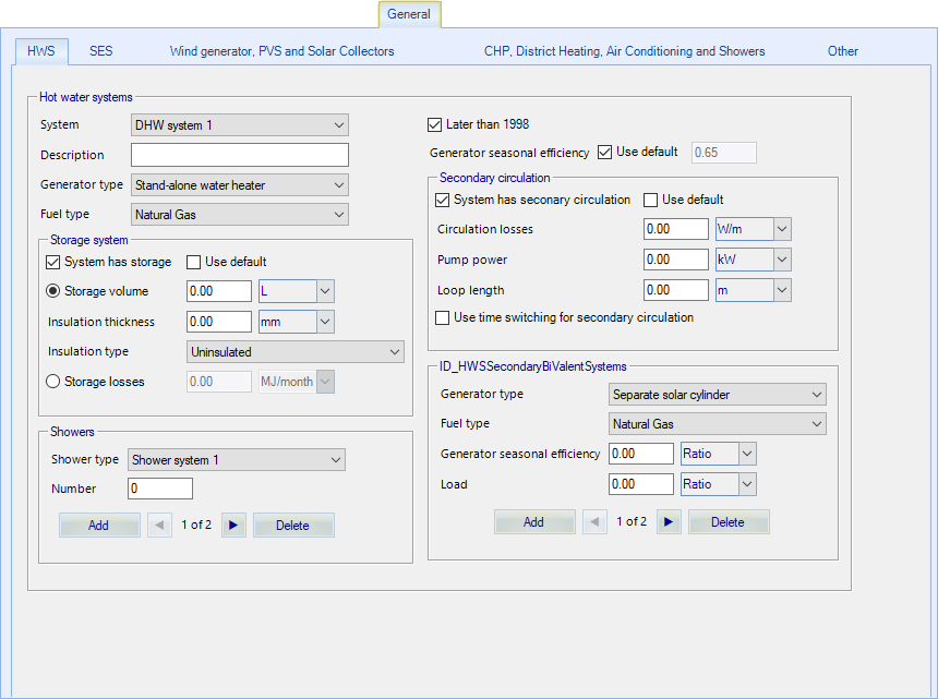
The Hot Water System specifications are set here.
- DHW system - Up to
20 different DHW systems can be defined. Each room is associated with a DHW
system. Each DHW system has a set of data to define the system.
- Description – each
DHW system has a unique name.
- Generator type –
select the type of DHW generator, this selection includes using the same heat
generator as the heating system.
- Fuel type – select
from list.
- Later than 1988 –
you can define whether the generator was installed after 1998.
- Generator seasonal
efficiency – the generator seasonal efficiency can be specified, or a default
value can be used.
Storage system – a hot water
storage system can be specified. If the Storage volume (litres) and the Storage
losses (MJ/month) are known, they can defined, otherwise a default will be
used.
Secondary circulation – if
there is secondary circulation with the DHW system it can be specified. If the
Circulation losses (W/m), Pump power (kW) and the pipe Loop length (metres) are
known, they can be defined, otherwise a default will be used. Time control can
also be specified for the secondary circulation.
If the Storage system or the Secondary circulation
system are set to use defaults, the program will fill in the data based on the
defaults used by SBEM.
The Bi-valent systems section allows a bivalent HWS
system to be setup. This is when the heating is supplied by two or more
different types of heat sources.
|
| SES
|
The Solar Energy System specifications are set
here.
- SES system - Up to
20 different SES systems can be defined. The following data must be defined for
each SES system.
- DHW system - Each
SES system must be designated to a DHW system so that the specific energy
saving due to solar power can be correctly counted.
- Description – each
SES system has a unique name.
- Area – solar panel
area (m2)
- Inclination – select
nearest inclination angle from the list.
- Orientation – select
the nearest orientation from the list.
- Multiplier – several
identical solar panels can be specified, all being designated to the DHW
system.
|
| Wind generator, PVS and Solar Collectors
|
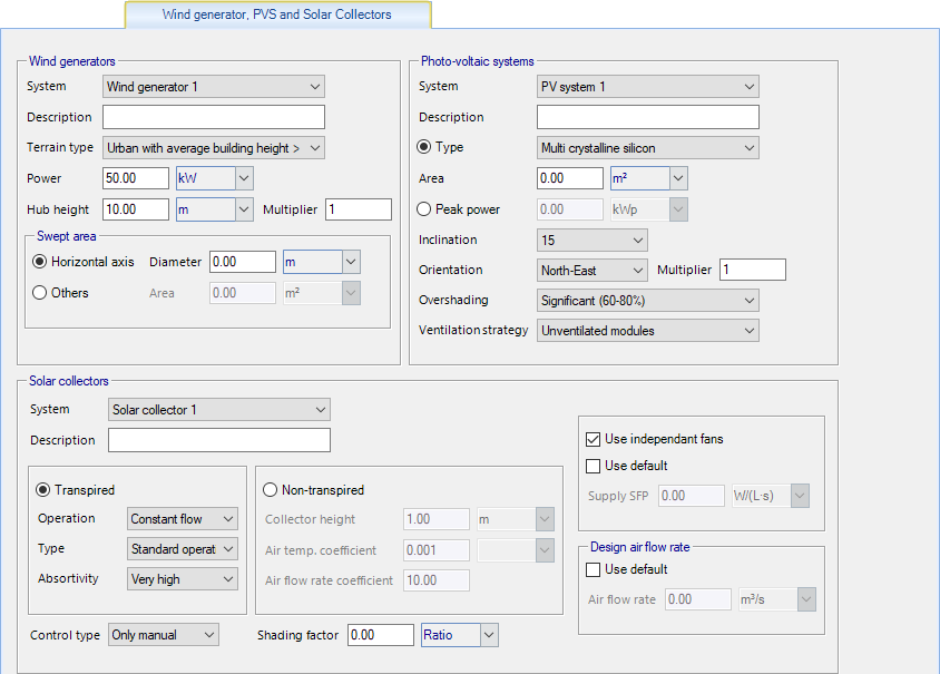
The
Wind generator specifications are set
here.
- System - Up to 20
different wind generators can be defined. Each wind generator has a set of data
associated with it.
- Name - each wind
generator has a unique name.
- Terrain type –
indicates the type of terrain around the generator.
- Hub height – Turbine
hub height.
- Power - delivered
electrical power at rated wind speed.
- Multiplier - several
identical wind generators can be specified.
The
swept area of the wind turbine is used to
calculate the area of air intercepted by the turbine rotor.
- Axial horizontal
wind turbines, enter the rotor diameter in m. The swept area is automatically
calculated as the area of the circle delineated by the turbine's blades.
- For any other type
of wind turbines including vertical axis wind turbines enter the turbine rotor
swept area, in m².
The
Solar collectors contains already defined
solar collectors, assigned if the room is served by solar collectors.
The
Photo-voltaic systems
specifications are set here.
- System - Up to 20
different PVS systems can be defined. Each PVS system has a set of data
associated with it.
- Description – each
PVS system has a unique name.
- Peak power – If the
peak power for the PV array is known it can be entered here otherwise the type
and area need to be entered.
- Type – The type of
module technology use in this PV panel.
- Area – photovoltaic
panel area, excluding the supporting construction.
- Inclination – select
nearest inclination angle from the list.
- Orientation – select
the nearest orientation from the list.
- Multiplier – several
identical photovoltaic panels can be specified, all being designated to the DHW
system.
- Overshading – This
refers to the percentage of the sky that is blocked by obstacles.
- Ventilation strategy
– This refers to the types ventilation between the PV module and its mounting
surface.
|
| CHP, District Heating, Air Conditioning and Showers
|
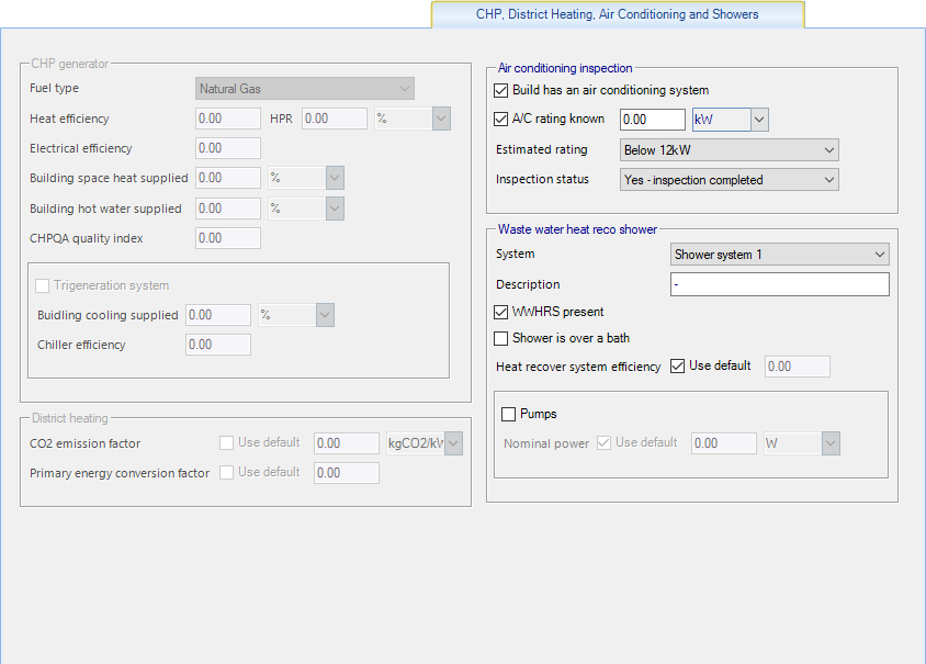
CHP generator - If the System
uses CHP check box has been checked for the heating system, CHP generator data
can be defined. The following data is defined for a CHP generator.
- Fuel type – select
from list.
- Heat efficiency –
The heat efficiency of the CHP generator.
- Electrical
efficiency – The electrical efficiency of the CHP generator.
- Boiler space heating
supplied – The proportion of space heating supplied to the building by the CHP
generator (%).
- Building DHW
supplied – The proportion of DHW supplied to the building by the CHP generator
(%).
- Heat to power ratio
– The annual useful heat supplied by the CHP generator divided by the annual
electricity generated (ratio).
District heating
- The CO2 emission factor for district
heating should reflect the average annual efficiency and fuel mix of the whole
district heating system. It should include all heat generating plant, including
any CHP, any waste heat recovery or heat dumping, the effect of heat losses in
distribution (external to the building), the emissions from electricity used
for pumping, and any other relevant carbon dioxide emissions. This option is
only available if district heating has been selected on any of the currently
selected HVAC system.
Air conditioning inspection
- This data is used for reporting purposing and is not used in the calculation.
If the building has an air conditioning system the
following can be entered:
- A/c rating - If
this is know it can be entered otherwise the estimated rating should be set.
- Estimated rating –
If the actual rating is unknown then an estimated range should be set.
- Inspection status –
The current status of the air conditioning inspection should be specified.
|
| Other
|
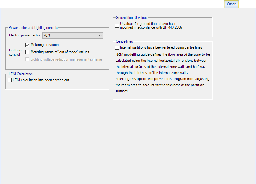
Power factor and Lighting
controls
- Electric power
factor – This is a measure of the actual electric power consumption to that
usually measured by the electric metre.
- Lighting control –
This gives a 5% controls correction to the lighting system is both options are
specified.
LENI Calculation - Specifies
whether a calculation following the Lighting Energy Numerical Indicator (LENI)
method has been carried out for the building as an alternative to complying
with the lighting efficacy standards specified in the Non-Domestic Building
Services Compliance Guide.
Ground floor U values - If
the U value of the ground floors have been modified in accordance to BR
443:2010, this needs to be specified. If the U values have not been modified
then SBEM will perform the modification
Centre lines - Typically DDB
rooms are entered using the internal edge of all room surfaces. The NCM
modelling guide defines the floor area of the zone to be calculated using the
internal horizontal dimensions between the internal surfaces of the external
zone walls and half-way through the thickness of the internal zone walls.
Selecting this option will prevent this program from
adjusting the room area to account for the thickness of the partition surfaces.
|